


From Blueprints to Digital Models: Understanding the CAD Conversion Process
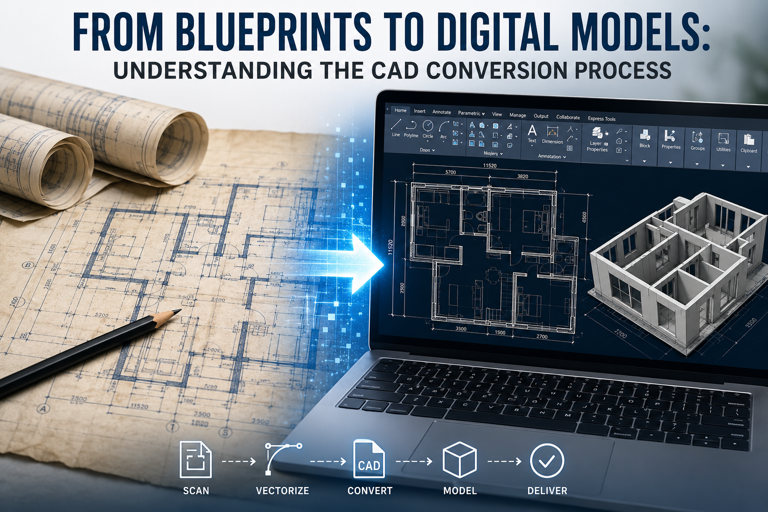
A blueprint can tell you almost everything you need about a building, component, or product—but if that blueprint is sitting in a filing cabinet, stored as a scanned image, or locked inside an outdated file format, using that information can be surprisingly difficult.
That is where CAD conversion comes in.
CAD conversion transforms paper drawings, scanned blueprints, PDFs, images, or legacy design files into editable digital drawings that can be used in modern design and engineering workflows. The process can range from straightforward PDF-to-DWG conversion to more involved work involving 2D drawings, 3D models, and BIM-ready data.
For companies dealing with large drawing archives or technically complex projects, working with experienced best cad conversion services can make the transition considerably easier.
But what actually happens between the moment an old blueprint is scanned and the moment a clean digital CAD file lands on your desktop? Let's walk through the process.
What Is CAD Conversion?
At its simplest, CAD conversion is the process of taking existing design information and recreating it in a computer-aided design environment.
Imagine you have a 20-year-old floor plan. The original may exist only as a paper drawing or a scanned PDF. You can look at it, print it, and send it to someone—but changing a wall, adjusting a dimension, or extracting individual elements isn't easy.
CAD conversion changes that.
Instead of a flat image, the drawing becomes a collection of editable CAD objects. Lines become lines. Circles become circles. Text becomes editable text. Dimensions, layers, blocks, and other elements can be organized so the drawing can be modified and reused.
This distinction is important. A converted CAD file should not simply look like the original blueprint. It should be structured in a way that makes the information useful for future design work.
From Paper and Scans to Editable CAD Files
There are several ways a drawing can enter the conversion process.
It might be:
- A physical paper blueprint
- A scanned architectural drawing
- A raster image
- A PDF
- An old CAD file
- A drawing exported from an obsolete design application
Each source presents different challenges.
A clean vector PDF, for example, may already contain recognizable lines and text. A faded paper drawing may require scanning, image cleanup, manual tracing, and extensive quality checking before the same information can be reconstructed digitally.
Autodesk's current learning material specifically describes digitizing old paper drawings and reusing them to create vector files, DWGs, and even 3D models.
Why Businesses Convert Legacy Drawings
Why go through all this trouble?
Because digital CAD data is much easier to work with.
Once a drawing is properly converted, teams can revise it, share it, measure it, archive it, reference it in new projects, and incorporate it into broader digital workflows.
That can be particularly valuable when a company is renovating an older building, updating legacy machinery, recreating a discontinued component, or managing decades of engineering documentation.
The CAD Conversion Process: Step by Step
Although the exact workflow varies from project to project, a professional CAD conversion typically follows several stages.
1. Reviewing and Assessing the Source Drawing
Before anyone starts tracing lines or running conversion software, the source material needs to be examined.
The conversion team will generally look at:
- File type
- Image resolution
- Drawing size
- Scale
- Line quality
- Text readability
- Dimensions and annotations
- Number of sheets
- Drawing complexity
- Required output format
This first assessment matters because there is no single conversion method that works perfectly for every drawing.
A clean, high-resolution scan might be suitable for software-assisted vectorization. A badly damaged historical blueprint may require considerably more manual work.
The team should also clarify what the final file needs to accomplish. Is it simply an editable 2D drawing? Does it need specific layer standards? Will it eventually be used to create a 3D model?
Answering those questions at the beginning prevents unnecessary rework later.
2. Scanning and Preparing Paper Blueprints
If the original exists only on paper, it first has to be digitized.
The quality of this scan can make a significant difference to the final result. Creases, stains, faded ink, distorted paper, shadows, and handwritten notes can all complicate the conversion.
The scanned image may therefore need to be cleaned before the CAD work begins.
Typical preparation can include:
- Straightening the image
- Removing unwanted noise
- Improving line visibility
- Correcting distortions
- Cropping unnecessary areas
- Adjusting contrast
- Preparing the image for vectorization
This is one reason a professional conversion process is more than simply running a scanned blueprint through an automated converter.
3. Raster-to-Vector Conversion
Here's where the transformation becomes particularly interesting.
A raster image is essentially made up of pixels. CAD drawings, on the other hand, rely on geometric objects that can be edited and manipulated.
Raster-to-vector conversion attempts to identify the geometry represented by those pixels and recreate it as CAD entities.
For example, a scanned line can become a CAD line or polyline. A circular feature can become a CAD circle. Text can potentially be recognized and recreated as editable text.
Autodesk's 2026 Raster Design documentation demonstrates vectorization of raster data into standard AutoCAD entities including lines, circles, multiline text, single-line text, 2D polylines, and 3D polylines.
However, automated vectorization isn't magic.
If the original scan contains overlapping lines, damaged geometry, handwritten annotations, or unclear symbols, the software may interpret them incorrectly. That's where human review becomes essential.
4. Recreating the Drawing in CAD
Once the source information has been prepared, the actual CAD reconstruction begins.
The goal is to reproduce the design intent—not merely copy what the pixels look like.
A conversion specialist may recreate:
- Walls and structural elements
- Mechanical components
- Electrical layouts
- Plumbing elements
- Dimensions
- Text
- Symbols
- Blocks
- Centerlines
- Hatches
- Other technical annotations
Depending on the project, some of this work can be automated while other portions are manually drafted.
The important thing is that the final geometry should be usable.
A drawing that looks perfect but contains poorly organized objects, incorrect dimensions, or inappropriate layers isn't necessarily a successful conversion.
5. Layering, Scaling, and Annotation
This is one of the less obvious but extremely important parts of CAD conversion.
A professional CAD file isn't just a collection of lines. Its structure matters.
Elements may need to be separated into appropriate layers—for example:
- Architectural
- Structural
- Electrical
- Plumbing
- Mechanical
- Dimensions
- Text
- Furniture
- Existing conditions
The exact layer structure depends on the project and the client's standards.
Scale and units also need to be verified. A drawing that is visually identical to the original but incorrectly scaled can cause serious problems when it is later used for estimating, fabrication, coordination, or construction.
Annotations need attention as well. Dimensions and notes should remain understandable and editable rather than becoming meaningless image fragments.
What Happens When a Blueprint Becomes a Digital Model?
One of the most useful things about CAD conversion is that it can become the starting point for additional digital work.
2D CAD: The First Step
For many projects, the immediate goal is a clean 2D CAD drawing.
A converted floor plan, elevation, site plan, mechanical drawing, or electrical layout can then be opened, measured, revised, and incorporated into a new design.
At this point, the project has already moved a long way from the original paper blueprint.
Moving From 2D Drawings to 3D Models
The next step may be 3D modeling.
A 2D drawing contains valuable geometric information, but it doesn't automatically become a complete 3D model. Someone still needs to interpret the drawings and build the appropriate three-dimensional geometry.
For example, floor plans and elevations can provide the information needed to construct walls, floors, openings, components, and other elements in a 3D environment.
Autodesk's digitization workflow specifically covers taking old drawings from raster data toward DWG and 3D-model workflows.
CAD and BIM Workflows
For architecture, engineering, and construction teams, the converted drawing may eventually become part of a BIM workflow.
That makes the quality and organization of the original conversion even more important.
A useful digital model needs more than visual similarity. The geometry, annotations, and data need to be structured appropriately for the intended application.
ISO 16792:2021, for example, addresses requirements for the preparation, revision, and presentation of digital product-definition data and supports both 3D model-only and 3D model-with-2D-drawing approaches. ISO currently lists a newer revision as under development.
Manual vs. Automated CAD Conversion
So, should CAD conversion be automated or done manually?
In practice, the best answer is often: both.
Where Automation Helps
Software-assisted conversion can be particularly useful when dealing with:
- Large numbers of similar drawings
- Clean scans
- Standard geometric elements
- Repetitive features
- Straightforward linework
- Batch processing
Automation can significantly reduce repetitive work and accelerate the first stage of conversion.
Where Human Expertise Still Matters
People are still needed when the drawing contains ambiguity.
Consider an old blueprint where two lines overlap, a dimension is difficult to read, or a symbol has been partially damaged.
Software may make an educated guess. A trained CAD professional can compare the surrounding geometry, dimensions, annotations, and design context to determine what the drawing actually means.
That difference can matter enormously in engineering and construction.
Why a Hybrid Approach Often Works Best
A hybrid workflow combines the speed of software with human judgment.
Software handles repetitive tasks. Specialists review, correct, organize, and validate the results.
This approach can be especially useful for large archives where manually recreating every single element from scratch would be unnecessarily slow, but relying entirely on automation could introduce errors.
Common Challenges in CAD Conversion
Not every blueprint makes the conversion process easy.
Poor-Quality or Damaged Blueprints
Old drawings may be faded, torn, stained, folded, or difficult to read.
Historical drawings can be especially challenging because the source itself may contain inconsistencies or incomplete information.
In these cases, the conversion team has to distinguish between an actual design feature and an artifact caused by damage or scanning.
Incorrect Scale or Units
Scale errors can be difficult to spot because a drawing can look perfectly normal on screen.
That's why critical dimensions and units should be checked against the source material.
If the converted drawing is later used for manufacturing or construction, a small scaling mistake can have consequences far beyond the CAD file itself.
Complicated Layer and Annotation Structures
Another common issue is organization.
A drawing can contain hundreds or thousands of elements. Putting everything onto a single layer may technically produce an editable file, but it doesn't produce a particularly useful one.
Proper organization makes future editing, coordination, and troubleshooting much easier.
Outdated or Incompatible File Formats
Legacy CAD files can create another challenge: software compatibility.
DWG remains AutoCAD's native drawing format, while DXF provides a tagged representation of drawing information that is widely used for data exchange.
Compatibility can also depend on the AutoCAD version involved. Autodesk's current documentation notes that newer AutoCAD versions can save drawings in earlier formats when files need to be shared with users running older software.
That means choosing an output format isn't simply a matter of picking the most recent file type. The receiving team's software and workflow should be considered too.
How to Choose the Right CAD Conversion Approach
Not every project needs the same level of conversion.
Consider the Source Material
Start by identifying what you're working with.
Is it:
- Paper?
- A scanned image?
- A vector PDF?
- An old DWG?
- A drawing from another CAD platform?
The answer will influence both the workflow and the amount of manual work required.
Consider the Required Output
Next, define what you actually need at the end.
You might require:
- Editable 2D CAD
- DWG
- DXF
- 3D CAD
- Revit
- Another specialized CAD format
The desired output should be established before conversion begins.
Consider Accuracy and Quality Requirements
A simple reference drawing may not require the same level of verification as a manufacturing component or construction document.
For technically sensitive projects, critical dimensions, layers, annotations, and geometry should receive additional attention.
Consider Project Volume and Turnaround
Converting one drawing is very different from converting an archive containing several thousand sheets.
For large projects, consistency becomes just as important as individual drawing accuracy. A standardized workflow can help maintain the same naming conventions, layer structures, quality checks, and output formats across the entire archive.
Industries That Benefit From CAD Conversion
CAD conversion isn't limited to one industry.
Architecture and Construction
Architectural firms frequently encounter older floor plans, elevations, and site drawings during renovation and refurbishment projects.
Converting those documents into CAD makes it easier to update existing designs and incorporate them into current workflows.
Manufacturing and Engineering
Manufacturers may have decades of component drawings stored in paper archives or outdated CAD formats.
Converting those drawings can make legacy designs searchable, editable, and reusable.
That can be particularly useful when a company needs to reproduce an older component or update an existing product.
Real Estate and Facilities Management
Building owners and facilities teams also benefit from digitized drawings.
Floor plans, as-built documentation, mechanical layouts, and other building records become much easier to manage when they are available as structured digital files.
Furniture, Millwork, and Product Design
CAD conversion can also help designers turn sketches and legacy drawings into usable digital geometry.
Once converted, those drawings can become a starting point for design revisions, detailed drafting, visualization, or 3D modeling.
How to Ensure a Converted CAD File Is Actually Useful
Getting a CAD file isn't necessarily the finish line.
The real question is whether the file is ready to use.
Don't Stop at Visual Similarity
Put the converted drawing side by side with the original.
Does everything line up?
Are dimensions correct?
Are annotations present?
Are important details missing?
Does the file behave like a CAD drawing rather than a traced picture?
These checks help distinguish a genuinely useful conversion from a superficial one.
Verify Dimensions and Scale
Critical measurements should be checked against the source.
If known dimensions are available, use them as reference points during quality control.
Check Layers and Objects
Open the layer manager and inspect the structure.
Are related elements grouped appropriately?
Are line types correct?
Can individual objects be edited?
Can someone else understand the drawing without having to reverse-engineer how it was created?
Test the File in the Intended CAD Software
Finally, open the completed file in the software that will actually be used for the project.
Try basic operations such as:
- Selecting objects
- Editing geometry
- Measuring distances
- Turning layers on and off
- Checking dimensions
- Printing or plotting
- Referencing the file in another drawing
This practical test can reveal problems that aren't obvious from simply viewing the drawing.
Final Thoughts: Turning Old Drawings Into Usable Digital Assets
CAD conversion is ultimately about more than changing a paper blueprint into a DWG file.
It is about taking information that is difficult to access or modify and turning it into something a modern design team can actually use.
The journey might look simple from the outside:
Blueprint → Scan → Clean-up → Vectorization → CAD reconstruction → Quality control → Digital model
But every stage matters.
A poor scan can create bad vector data. Bad vector data can create inaccurate geometry. Poorly structured geometry can make a CAD file frustrating to edit. And small errors can become much bigger problems when the drawing moves into construction, manufacturing, coordination, or BIM.
That is why a thoughtful CAD conversion process combines suitable software, technical drafting knowledge, careful quality checks, and a clear understanding of the intended final workflow.
For organizations sitting on years of paper drawings, scanned plans, or legacy CAD files, conversion can turn those archives from static records into valuable digital assets—ready to be edited, reused, coordinated, and built upon.

 English
 Arabic
 French
 Spanish
 Portuguese
 Turkish
 Dutch
Dutch
 Italiano
 Russian
 Romaian
 Portuguese (Brazil)
 Greek
Greek