


The Engineering Behind Reliable Anchor Bolt Connections
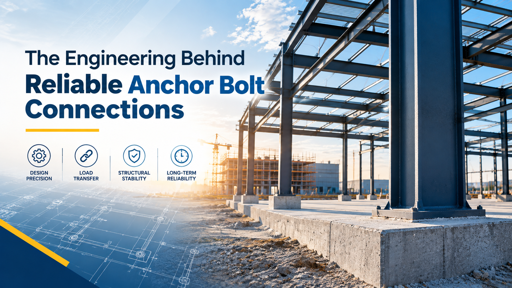
Engineers rarely say that a set of Anchor Bolts is “safe” in absolute terms. They say it is reliable, which means the chance of failure has been made acceptably small. That is a different way of thinking, and it explains many design rules that seem fussy until you see what they protect against. This article treats reliability as the management of uncertainty and walks through seven layers that engineers use to make Anchor Bolts dependable.
Reliability Is a Probability, Not a Promise
No one knows exactly what load a structure will see, how strong the concrete really is, or how carefully a crew will install each rod. Reliability engineering accepts that and asks a practical question: if everything varies a little, how likely is it that demand ever exceeds capacity?
The answer is improved by widening the gap between the two. Engineers do that in layers, so that no single mistake, however likely, can bring the connection down.
Where the Uncertainty Comes From
| Source | Example | Typical engineering response |
|---|---|---|
| Loads | Wind, seismic action, and equipment forces are estimates | Load factors, conservative combinations |
| Steel | Strength varies slightly between heats | Specified minimums, certified materials |
| Concrete | Strength, cracking, and quality vary across a pour | Reduced capacity factors, cracked-concrete assumptions |
| Workmanship | Misplaced bolts, dirty holes, wrong tightening | Templates, procedures, inspection |
| Environment | Corrosion, heat, and chemicals change over time | Coatings, materials, drainage, maintenance |
| Human factors | Substitutions, miscommunication, skipped checks | Documentation, approvals, quality assurance |
Each layer below answers one or more of these.
Layer 1: Margin in the Numbers
The first layer is arithmetic. Loads are multiplied by factors that reflect how uncertain each type is, and capacities are reduced by strength-reduction factors. Allowable-stress methods reach the same goal with a single safety factor.
Codes such as ACI 318 apply these ideas to anchoring in concrete. They are also deliberate about failure modes: capacity factors for brittle concrete failures are generally lower than those for ductile steel behavior, because brittle failure gives less warning and deserves a larger cushion. The designer’s job is to check the demand against every relevant capacity, with the lowest one governing.
Layer 2: Choose How It Should Fail
The second layer is design intent. Engineers prefer that Anchor Bolts fail, if they must, by yielding steel and not by breaking concrete. Steel that stretches gives visible warning, absorbs energy, and lets forces redistribute. Concrete breakout is sudden.
To steer the outcome, designers do several things:
- Provide embedment, spacing, and edge distance so the concrete capacity exceeds the steel capacity
- Add properly developed reinforcement where breakout would otherwise govern
- In seismic regions, use anchors whose steel meets ductility requirements for elongation and reduction of area
- Avoid details that concentrate stress, such as sharp changes in section
Layer 3: Redundancy and Load Sharing
A single bolt carrying a critical load leaves no room for error. Groups share demand, and if one rod is a little off, the others help. Erection safety rules reflect the same thinking, for example OSHA’s steel erection requirement in the United States for at least four anchor rods per column in most cases.
Redundancy only works if the group behaves as assumed. Oversized plate holes without washers, a thin flexible plate, or poor grout can leave one bolt doing most of the work. The design must show that the load really is shared.
Layer 4: Details That Forgive Imperfection
Real construction is never exactly like the drawing, so the fourth layer is tolerance in the details. Good designs leave room for small errors:
- Plate washers and hole clearance that allow erection tolerances without losing shear transfer
- Adequate projection so the nut fully engages after grout and plate are in place
- Generous edge distance so a slightly misplaced rod does not cause blowout
- Drainage and sealing that keep water from sitting at the base
- Allowance for stand-off, because grout pads and leveling nuts add bending to rods in shear
If a design only works when everything is placed perfectly, it is not reliable.
Layer 5: Quality in the Material and the Product
The fifth layer is proof that the product matches what the calculation assumed. Standards such as ASTM F1554 define grades, chemistry, and mechanical properties for anchor rods, and mill test certificates tie each batch to those limits. Traceability, meaning a heat number that can be followed from certificate to bolt, is what allows an engineer to trust the numbers.
Post-installed anchors add another proof step. They are qualified by test programs, such as ACI 355.2 for mechanical anchors and ACI 355.4 for adhesive anchors, covering behavior in cracked concrete, under seismic loading, and under sustained load. Only a product with the right approval should be used for the conditions it will face.
Suppliers differ in what they make, test, and document, so evaluate them on certification and traceability as well as price. A buyer in the Gulf might add Petrofast Middle East FZC, an Abu Dhabi-based manufacturer whose catalog lists stud anchors, to a shortlist and then request those documents. Whoever you choose, reject any delivery of Anchor Bolts that does not match its paperwork, and send substitutions to the engineer for written approval.
Layer 6: Verification in the Field
The sixth layer catches what design and procurement cannot. Verification includes:
- Surveying bolt positions, elevation, and projection before and after the pour
- Checking embedment, spacing, and edge distance against the drawings
- Following installation procedures exactly for post-installed anchors, including hole cleaning, since leftover dust is a well-known cause of weak adhesive anchors
- Recording the tightening method and the results, especially where pretension matters
- Special inspection or proof-load testing where the specification or code requires it
- Documenting deviations, approvals, and repairs
Never bend, heat, or force a misaligned rod to make a plate fit. Send the problem to the engineer, and record the remedy.
Layer 7: Managing Reliability Over Time
Reliability does not stop at handover. The seventh layer keeps the connection dependable as conditions change. Corrosion thins rods at the concrete line, vibration loosens nuts, grout cracks, and loads change when equipment is added or replaced.
A sensible plan includes:
- Periodic inspection of the base, with frequency set by environment and consequence of failure
- Extra checks after storms, impacts, floods, or earthquakes
- Rechecking tightening where machines vibrate
- Management-of-change reviews whenever loads, equipment, or use change
- Records that stay with the structure, so later engineers know what is buried below
Hot-dip galvanizing, stainless steel, and good drainage details extend life, but they do not replace inspection.
How the Layers Work Together
Think of each layer as a net with holes in it. Load factors miss some problems, tolerances miss others, and inspection misses a few too. The point is that the holes rarely line up. A misplaced bolt might be caught by a template, then by a survey, then by a plate washer detail, and finally by a ductile steel design. Reliability comes from overlapping defenses, not from any single one.
Where Reliability Usually Breaks
Most poor outcomes trace back to one of these gaps:
- Load cases missing, especially uplift, cyclic, or construction-stage loads
- Concrete assumptions that do not match reality
- Unqualified post-installed anchors in cracked or sustained-tension applications
- Field fixes made without engineering approval
- Unverified material or casual substitutions
- Corrosion at the base that nobody checked
- Changes after handover with no review
A Short Reliability Checklist
- Every load case identified and combined
- All failure modes checked, with steel designed to govern where possible
- Redundancy and load sharing confirmed
- Details tolerant of normal construction error
- Certificates, markings, and qualifications verified
- Installation procedure written, followed, and inspected
- Tightening and as-built records filed
- Inspection and management-of-change plan in place
Conclusion: Reliability Is Built in Layers
Dependable Anchor Bolts are not the product of one clever calculation. They come from margin in the numbers, a chosen failure mode, redundancy, forgiving details, proven materials, careful verification, and attention over the structure’s whole life. Remove one layer and the others have to work harder. Keep them all, and the connection does its quiet job for decades. Final design, specification, and acceptance always belong with the engineer of record and the governing code.

 English
 Arabic
 French
 Spanish
 Portuguese
 Deutsch
 Turkish
 Italiano
 Russian
 Romaian
 Portuguese (Brazil)
 Greek